Redstone Pulsed Magnetron Transmitter
750 – 4500 KW, 2480 – 5910 MHz.
| SPECIFICATIONS | ||||||
|---|---|---|---|---|---|---|
| BAND | FREQUENCY GHz | PEAK POWER KW | DUTY | MAX PULSE WIDTH µS | WAVEGUIDE | |
| S10 | 2.48-2.70 | 750 | .0012 | 2 | WR284 | |
| S20 | 2.75-2.85 | 4500 | .0001 | 2.5 | WR284 | |
| S30 | 2.993-3.002 | 2600 | .001 | 5 | WR284 | |
| S40 | 3.1-3.5 | 880 | .0011 | 2.5 | WR284 | |
| S50 | 3.5-3.9 | 750 | .0012 | 2 | WR284 | |
| C10 | 4.1-4.4 | 1000 | .00125 | 3.5 | WR187 | |
| C20 | 4.9-5.1 | 1500 | .0011 | 1.3 | WR187 | |
| C30 | 5.39-5.91 | 1000 | .0011 | 3 | WR187 | |
Primary power source: 208VAC, 3 PHASE, 70 AMPS,5 WIRE
Dimensions: 31.5″DEEP X 80″ TALL X 31.5′ LONG
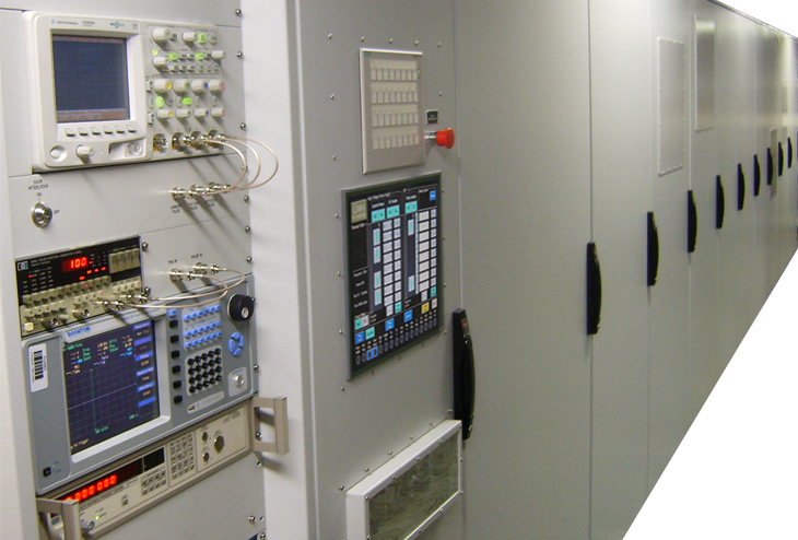
DESCRIPTION: The RPMT generates RF power from eight magnetrons that are pulsed by a single modulator. Five magnetron-ready bays are included for future installation of magentrons. Pulse control comes from a panel-mounted pulse generator. One magnetron can transmit at a time while a second magnetron is warming up or in standby for transmission. RF output is from one central location where the waveguide exits the system through the floor.
An operator controls the transmitter from a touch screen panel and push button control panel at one end of the system. Magnetron power and frequency can be controlled from the touch screen. Instrumentation is provided to monitor output power and frquency. Instruments also monitor voltage and current pulse amplitude and shape as well as RF pulse shape. A second channel is available on the power meter for calibration of the field.
The systems is protected by fault monitors that include Pulse Width, Filament Voltage, Average Current, Duty Cycle, Air Flow, Wave Guide Pressure, Wave Guide Switch Position, and Wave Guide Arc. An emergency stop switch is provided. Door open/closed conditions are also monitored.
The transmitter has a built-in liquid to air heat exchanger that vents excess heat to the room. The entire system is housed in 12 cabinets that comprise a unit measuring 31.5″ wide x 80″ tall x 31.5′ long.