Magnetron transmitters offer the lowest cost per watt solution for RF sources. Magnetrons are vacuum tube oscillators (not amplifiers). They output high-power RF pulses when pulsed with high voltage. They also require a specific filament voltage and air or liquid cooling. Pulse widths are in the 1–4 uS range, with duties close to .001. They are used in medical systems, particle accelerators, security inspection systems, RADAR systems, counter-drone measures, plasma generation, RF research and many other areas. In applications requiring a true RF amplifier rather than an oscillator, a klystron transmitter may be the preferred choice.
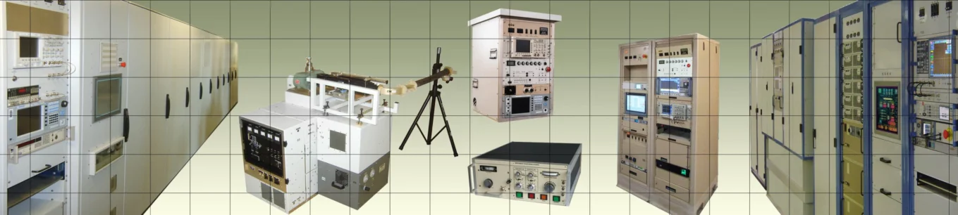
H6 Systems Inc. builds transmitters based on the magnetrons listed below and many others. Our Tube Finder tool can be used to find a magnetron to design your transmitter around. If you don’t see what you need, give us a call; not all tubes are listed. Use our RF System Builder to specify your transmitter and get a quote. Our Field Strength Calculator will help you estimate the necessary tube power to generate your field.
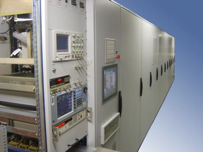
Our Full or Partial Turnkey System Integration Service

We can build your partial or full turnkey system interfaced with your controls or our controls (mechanical, touch screen, or web-based Graphical User Interface). Customers find that the transmitter is only part of the system. Output handling from the transmitter to the antenna or load involves decisions on waveguide type, waveguide size, waveguide material, pressure, dielectric gas, humidity, coupling type, dB level, reflected detection, arc detection, flange type, pressure gasket type, dryer type, vendor, delivery time, price, mechanical attenuator, isolator, load type, load cooling, pressure window, average power limit, and peak power limit.
H6 Systems offers assistance on these items including design, selection and procurement so you will save time and have a single source for your full system. To begin outlining your configuration, use the RF System Builder tool, or contact H6 Systems to discuss your requirements.
A Partial List of Magnetrons Used in H6 Systems Transmitters:
L-4220, L-4235, L-4339, L-4524, L-4555, PM-100U, PM-119U, PM-127S, PM-130S, PM-158U, PM-200C, PM-320C-T, PM-500S, PM-550X, PM-670C, PM-750S, PM-920S, VMA-3057, VMA-3078, VMC-1130, VMC-1294GD, VML-3146, VMK-3055, VMK-3056, VMK-3076, VMK-3077, VMU-1357, VMU-1379, VMS-3166
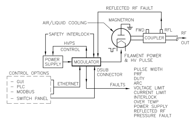
Block Diagram of a Magnetron Transmitter
Magnetron Transmitter FAQs
What is a magnetron transmitter?
A magnetron transmitter is a high-power RF pulse source that uses a magnetron vacuum tube to generate microwave energy directly, rather than amplifying an external RF signal.
Why choose a magnetron transmitter instead of a klystron?
Magnetron transmitters are often chosen when lowest cost per watt and high peak power are the primary requirements, and precise phase or frequency control is not required.
What information is needed to specify a magnetron transmitter?
To specify a magnetron transmitter, it is helpful to know the required operating frequency, peak power, average power, pulse width, duty cycle, load type, waveguide size, cooling method, control interface, and any protection requirements. If those details are not finalized, H6 Systems can help review the application and recommend a transmitter configuration.
Are there different types of magnetrons?
Yes. There are conventional, coaxial, pulsed, continuous wave (CW), and relativistic magnetrons, as well as older types such as split-anode and reflex designs. All modern magnetrons use resonant cavities to increase power output. Coaxial magnetrons include an additional structure around the anode to improve stability. CW magnetrons output energy continuously, while pulsed magnetrons generate short, high-power pulses. Relativistic magnetrons operate at much higher voltages and can produce extremely high power levels.
How do I handle the output from a magnetron?
Magnetrons typically output microwave energy into waveguide sized for the operating frequency. A directional coupler can measure forward and reflected power. If the load is not well matched, an isolator or matching network may be required to protect the magnetron. For pulsed systems, a properly designed attenuator can vary output power without distorting the pulse shape.
What makes a magnetron work?
Electrons are emitted from the heated cathode (except in relativistic magnetrons). High voltage applied between the cathode and anode, in the presence of a magnetic field, causes the electrons to orbit rather than travel directly across the vacuum gap. These electron motions excite resonant cavities in the anode structure, creating microwave oscillations that couple into a waveguide output.
In pulsed magnetrons, voltage pulses typically range from 5 kV to 70 kV. Continuous wave magnetrons use high voltage DC. Higher power systems may require pressurized waveguide using dry air or SF6 to prevent breakdown.
What kind of controls would a magnetron transmitter have?
Magnetron transmitters may include controls for voltage, pulse width, pulse repetition frequency (PRF), magnetic field strength, and in some cases limited mechanical frequency tuning. Adjusting voltage or magnetic field can influence output power, although pulse shape may be affected in pulsed systems.
Protection and fault limits often include peak current, average current, voltage, reflected RF, duty cycle, and thermal limits. Controls may be implemented through mechanical interfaces or computer-based systems.
How can I configure a magnetron transmitter system for my application?
H6 Systems’ RF System Builder can help you explore compatible system components and start building a magnetron transmitter configuration for your application. It is a useful starting point for identifying options before requesting a quote.
Build a Custom Magnetron-Based Transmitter System Online

Use our RF System Builder Tool to build a complete or partial custom magnetron-based transmitter system in minutes, completely free! Then get a fast, tailored quote from our engineers.